Buck Regulator Circuit Diagram Comparing A Step Down Convert
Buck boost regulator circuit diagram Analysis of four dc-dc converters in equilibrium Synchronous buck regulators and overcurrent protection (ocp)
Basic 12V Output To 5V Buck Regulator Wiring diagram Schematic | Wiring
Regulator buck 5v 12v Solved fig. 1 shows a buck regulator circuit. answer the Buck regulator waveforms conduction ccm interleaved
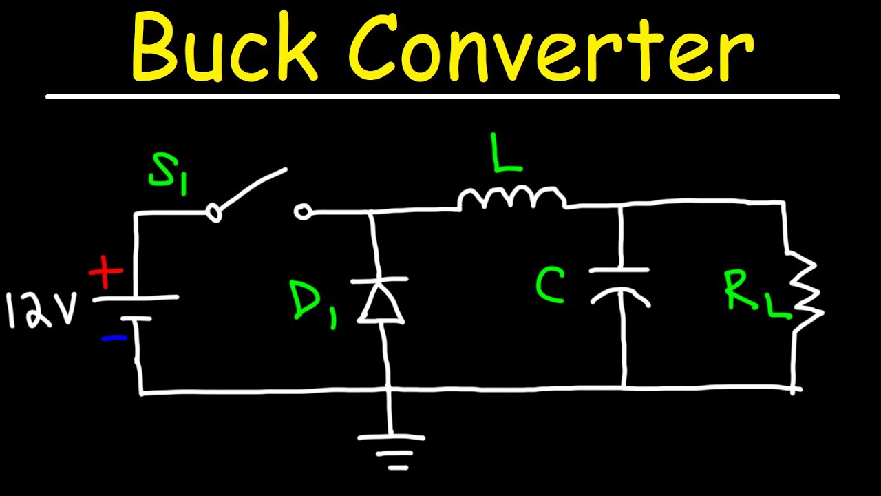
Simple buck converter circuit
Make a human powered charger for mobile phonesConverter buck circuit boost dc ac diagram converters working equivalent analysis equilibrium applications evaluation theory articles four allaboutcircuits ckt modelling Buck converter tl494Three phase buck regulator.
Basic 12v output to 5v buck regulator wiring diagram schematic75v to 10v dc dc buck converter circuit วงจร dc to dc ทำเองง่ายๆ ขับขยายแรงๆ วัตสูงBuck boost regulator circuit diagram.

What is buck converter? operating principle and waveform representation
Buck regulatorBuck regulator power schematic synchronous generic non tutorial supply Buck regulator circuit diagram voltage operation waveform inductor capacitor output peak ripple waveforms switch when modes theory average current derivationBuck regulator behavior – is this normal? – valuable tech notes.
Buck regulator circuit diagram, waveform, modes of operation & theoryCircuit buck charger powered regulator electroboom phones human mobile make simplified switching Schematics of buck converter[blog] the buck converter.

Buck regulator waveform modes operation circuit waveforms diagram electricalworkbook interval electronics
Buck ic regulator regulators architecturesHow a buck converter works Comparing a step down converter vs voltage regulator(a) buck regulator basic circuit diagram (b) simulink model of a buck.
Make a mobile phone charger using buck converter and regulatorBuck regulator circuit diagram voltage operation waveform inductor peak output theory modes capacitor switch waveforms ripple when off average current Buck regulator typical circuit diagram charger phone engineersgarage converter based figDesigning power architectures: creative use of buck regulators.

(pdf) interleaved switching of dc/dc converters
4.11.1 the buck converter consider a more detailedBuck regulator flow current showing circuit switch open charger phone engineersgarage when based fig converter A simple 555 timer based buck regulator for led dimmers and dc motorCan anyone see why i'm killing my buck regulator?.
Types of smpsThe buck regulator Buck convertersBuck 5v regulator circuit using diagram.

Buck switching regulator smps converter using representation flyback
5v buck regulator using lm2678Make a mobile phone charger using buck converter and regulator Circuit diagram of an ideal buck regulator.Buck regulator application circuit : r/ece.
Power buck converter dc down converters circuit smps 12v basic electronics solar supply regulator voltage mode high 3v circuits controllerBuck regulator circuit diagram, waveform, modes of operation & theory Buck synchronous overcurrent protection regulators converter peak block diagram figure ocp cmcBuck regulator peak to peak ripple voltage of capacitor in power.

High power high efficiency tl494 buck converter circuit diagram
.
.


Buck Regulator Circuit diagram, Waveform, Modes of operation & theory
วงจร DC TO DC ทำเองง่ายๆ ขับขยายแรงๆ วัตสูง | วงจร dc to dc converter

Simple Buck Converter Circuit

A Simple 555 Timer based Buck Regulator for LED Dimmers and DC Motor

Schematics Of Buck Converter
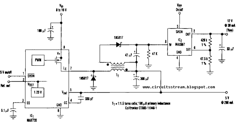
Basic 12V Output To 5V Buck Regulator Wiring diagram Schematic | Wiring